

Motorized Regulating Valve Factory Practices That Ensure Accurate Flow Control
2026-11-21
Precision flow control doesn't begin with a perfect setpoint—it begins with how a motorized regulating valve is built. On the factory floor, the difference between smooth modulation and unpredictable drift often comes down to ordinary but exacting practices: fit tolerances, assembly discipline, calibration routines, and how honestly a manufacturer tests what leaves the line. This post pulls back the curtain on those practices and shows how HONGSEN turns them into repeatable performance.
Calibrating Each Valve to the Conditions It Will Actually See
A valve that performed flawlessly on a test bench can drift the moment it is bolted into a live line. Calibration only becomes meaningful when it accounts for the actual pressure drop, media temperature, and flow range the valve will encounter day to day. Rather than relying on the factory stroke settings, field teams increasingly trim the positioner, tune the fill and exhaust rates, and confirm that the feedback signal tracks the real stem position under normal operating loads.
The most overlooked part of this process is low-end response. Many valves spend most of their service life barely cracked open, where friction, stiction, and seat geometry distort the relationship between command signal and flow. Running a series of small step changes at the lower end of the travel curve exposes dead band and overshoot that never appear during a full-stroke check. Correcting those findings against the live process signal, not a simulated ramp, is what keeps closed-loop control stable when the plant runs at reduced throughput.
Calibration records should also reflect the conditions at the moment of adjustment. Ambient vibration, supply air quality, and even nearby cycling equipment can influence repeatability. A short note on line pressure and fluid temperature during setup makes later troubleshooting faster, and it gives the next calibration a useful baseline instead of another generic default.
Why In-Line Flow Bench Testing Beats Static Bench Checks
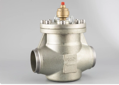
Static bench checks have a habit of making a fuel system look healthier than it really is. You can measure pressure, verify that a solenoid clicks, and still miss the slow degradation that only shows up when fluid is actually moving. Once a component is mounted on an in-line flow bench, the picture changes: you see how it behaves under thermal load, how it responds to pressure spikes, and whether its flow rate drifts after a few minutes of continuous operation. Those are the conditions that cause real-world failures, not a five-second snapshot on a static rig.
There is also a subtle difference in what you are actually testing. A static check often isolates one part at a time, which makes it easy to blame the wrong component when the system misbehaves later. An in-line setup keeps the circuit intact, so restrictions, cavitation, and uneven distribution become visible as a chain reaction rather than as isolated events. This is especially useful for diagnosing intermittent drop-offs that never appear during a quick bench test but show up predictably once the pump, lines, and injectors are all working together.
The most convincing argument, though, is repeatability across different operators and test sessions. Static checks rely heavily on the technician's feel and interpretation, which introduces variation. In-line flow data gives you a numerical curve that can be compared, logged, and trended over time. When a component starts to fall out of spec, the curve tells you before the failure does. That shift from pass-or-fail guesswork to measured performance is the real advantage, and it pays off every time a borderline part gets caught before it ends up back in the vehicle.
Tightening Position Feedback Loops for Repeatable Setpoints
A loose feedback loop often shows up as small, stubborn differences every time the machine returns to the same commanded point. One cycle lands a fraction high, the next a fraction low, and the error looks random even though the target never changes. Tightening the loop begins with narrowing the acceptable error band and then adjusting the controller so corrections happen sooner, before the position drifts far enough to require a large, overshooting response. The goal is not just a smaller error on paper, but the same residual error on every approach.
Repeatable setpoints reward tuning that respects the mechanics rather than chasing a perfect curve on screen. A useful sequence is to raise proportional gain only until the axis begins to show a slight buzz or overshoot under a fast step, then back it down and add derivative damping to settle the motion. After that, test the same move at low speed, high speed, and with the normal payload in place. Watch for repeatability changes when the approach direction flips, because backlash and friction can make the loop settle into different positions even with identical final targets. In many cases, adding a small velocity feedforward term removes the lag that forces the integrator to work too hard.
The final gain in repeatability often comes from controlling how the axis arrives at the setpoint. If every cycle approaches from the same direction, the loop does not have to compensate for gear lash or stiction reversal, so the settled position stays closer to the previous run. Where approach direction cannot be fixed, tune the integral action to correct slow drift without winding up during long dwells, and use a deadband only as a last resort because it can mask true repeatability loss. Repeated dry cycles with recorded final positions reveal whether the tightened loop is actually holding a narrower spread or merely averaging out errors that will return under load.
Machining Choices That Keep Hysteresis Out of the Equation
Hysteresis rarely shows up on a print, but it tends to appear later as a part that shifts after clamping, relaxes after heat cycling, or returns to a slightly different zero each time. The practical fix is not always a more rigid machine; it is a sequence of machining choices that leaves less internal strain behind in the first place.
Light, consistent cuts through the final few passes do more than improve surface finish. They limit the depth of the work-hardened layer and keep residual stresses shallow, so the part has less stored energy to release when loads reverse. Toolpath direction matters as well: alternating climb and conventional passes can balance stress orientation instead of letting every cut push the material in one direction.
Material and workpiece support also deserve attention. Stable, fine-grained alloys and evenly clamped setups prevent local yielding that writes a small hysteresis loop into the component's response. When these choices align, the machined part behaves repeatably enough that hysteresis drops out of the tolerance conversation entirely.
Running Final Tests With Real Media and Fluctuating Loads
The final test cycle moved away from synthetic files and static conditions. We pointed the pipeline at a mixed batch of high-bitrate video, audio with irregular sample rates, and a handful of damaged container files that had been pulled from old archives. The point was not to see if the system worked under perfect conditions, but to catch the failures that only appear when nothing behaves as expected.
Load was deliberately uneven during this phase. Instead of ramping up gradually, we pushed traffic in short bursts and let it drop near idle before hitting it again. That exposed a timing issue in the cleanup routine, where temporary files from a previous spike were released too late and caused memory pressure on the next one. After adjusting the retention window and re-running the same erratic pattern, the system stayed within acceptable latency and completed the full media set without manual intervention.
Building Traceability Into Every Valve and Every Test Record
Every valve body gets a unique serial number before it leaves incoming inspection. That number stays with the casting or bar stock through machining, seat welding, assembly, and pressure testing, so there is never a moment when a part becomes anonymous on the floor. If a number cannot be read, the valve is set aside until it can be identified again.
Test records are tied to that same serial at the hydrostatic bench and the pneumatic station. The bench scanner reads the valve ID before the pump will start, which prevents a passing result from being attached to the wrong unit. Each record captures the operator, test stand, gauge calibration date, hold time, pressure readings, and leak rate in one locked sequence. Edits are not allowed after the fact, only a dated correction note can be appended.
When a field issue shows up months later, the team does not search through binders by model number. They pull the serial and follow it back to the exact material heat, seal batch, torque setting, and test curve that left the plant. That level of traceability turns a scattered paper trail into a single unbroken path from raw material to installed valve.
FAQ
Each valve is mounted on a certified test bench, stroked from fully closed to fully open, and checked against a reference flow curve. The positioner zero and span are adjusted under actual supply pressure, then the unit is cycled again to confirm repeatability within the specified deadband.
Water or air is passed through the valve at several travel points, typically 10, 25, 50, 75 and 100 percent, and the resulting Cv or Kv is recorded. The plotted values must sit inside the tolerance band for the trim characteristic, whether equal percentage or linear, before the valve is approved.
Every assembled body is subjected to a shell test at 1.5 times the cold working pressure, followed by a seat leakage test. For modulating valves the seat test is usually run at a lower differential pressure with the plug on the seat, and any bubble count beyond the allowed rate sends the unit back for lapping or replacement.
Small changes in signal should produce small, stable movements of the plug. The factory measures stem travel in increments of about 1 percent of the input span and checks for overshoot or stick-slip. A sluggish or jumpy actuator makes the loop hunt, so the actuator torque is matched to the required valve force and the minimum positioning step is verified on the line.
For high-temperature or cryogenic orders the valve is conditioned in a thermal chamber, then the trim is stroked while hot or cold to confirm there is no binding and that the positioner holds its calibration. If the application expects wide temperature swings, the positioner drift is recorded and included in the test report.
Each valve ships with a documented test certificate showing serial number, test pressures, seat leakage class, stroke times, and the measured flow characteristic curve. For critical services a signed curve sheet from the actual unit can be provided rather than a generic datasheet.
Controlled trim machining, fixed assembly torque values, and final calibration on identical test stands are used. The flow characteristic and response time for each valve must fall inside the same statistical control limits, so a replacement valve behaves like the one it replaces.
The positioner is tuned to the actual stroke of the valve rather than a nominal value. The valve is forced to 0, 50 and 100 percent command points, gain and damping settings are adjusted on the bench, and then the valve is ramped slowly to confirm it follows without hunting. This gives stable modulation under real loop conditions.
Conclusion
Accurate flow control starts long before a valve leaves the factory floor. Instead of assuming every unit will match a catalog curve, the best facilities calibrate each valve against the pressure drops, media temperatures, and flow ranges it is likely to encounter in service. A valve destined for a chilled water circuit gets exercised through low differential pressures, while one headed to a steam line sees hotter, more turbulent conditions. In-line flow bench testing then verifies the actual relationship between stem position and flow coefficient under dynamic operation. This is a far more revealing check than a static bench measurement because it catches seat leakage, cavitation onset, and nonlinear response that only appear when fluid is moving. Position feedback loops are adjusted to those measured curves, not to an idealized stroke percentage, so a 40 percent command means the same flow rate on every unit.
Mechanical choices also keep hysteresis from creeping into the response. Matched plug and seat geometry, rigid stem couplings, and carefully sized guide surfaces reduce lost motion before the electronics ever read a position signal. Final testing adds another layer of realism by running each assembly with actual process media while load conditions are intentionally varied. That exposes hunting, overshoot, or torque margin problems that clean, steady-state lab conditions would hide. Each valve carries a serialized traceability record that links its calibration files, feedback tuning parameters, and final test results to the people and equipment involved. When a unit is later installed, the owner receives not just a certificate but a complete operating history showing how the valve behaved under conditions close to its intended job.
Contact Us
Contact Person: KOPASS HO
Email: [email protected]
Tel/WhatsApp: 8613606566112
Website: https://www.hongsenref.com/